Yes this article is actually about how to figure out connecting a stepper motor to your stepper motor driver.
This article is needed because there is no actual standard set up (or I can't find) for the naming of pins in stepper motor and the naming are extremely frustrating and confusing, they are so confusing because 1A and A1 can totally different pins!
In this post I attempt to connect all the random names flying around out there and create a clear guide using which you (and future me) can connect stepper motors no matter that naming (or pain) world throws at us.
Actual attempt is to tell the naming, and also how to figure out connection by knowing the basics of stepper motor. If you know and understand the basic you don't really need the convention
Now since I am done with my ranting/monologue following is the information which you care about
We have two player in our stepper motor setup
- Stepper motor
- Motor drive
Stepper Motor
Basic Idea behind stepper motor is to put a permanent magnet in the center which will be the shaft and put electromagnets in defined location around the shaft and pull the magnet by activating the electromagnets one by one to have defined rotation of shaft on which permanent magnet is attached.
If you want to understand detailed inner working of Stepper working, check out it this brilliant video, where the creator tears down a real motor and shows the working https://www.youtube.com/watch?v=6jkcoQ92cFk

Motor Driver
Motor driver most commonly controls the direction and magnitude of current through a coil of motor using H-Bridge. Following image shows basic depiction of how circuit is internally wired.
Very detailed understanding of H-Bridge and how circuit works: http://www.modularcircuits.com/blog/articles/h-bridge-secrets/h-bridges-the-basics/

Basic depiction of how the Motor Driver controls the Stepper Motor. Credits: TI
Connecting both of them
Main Idea is to connect two/three wires of coil to same H-Bridge, as shown in above picture.
The datasheets of motor driver will always have clear explanation of coil connection, they will might also a connection marking on the pin to tell which lead of coil connects where
Problem is on the stepper motor side, it's not clear which wiring or the pin on the connector coming out of the stepper motor connects to which coil. Sometimes there will be no adequate information in datasheet or in many cases there is just no datasheet (lols (lot of long sobbing))
So rest of the blog is just about figuring that out. Ha Ha hah ☹️. (Yes this is the whole point of this blog)
Connection marking
Following is how connections are marked in the stepper motor system, both on the stepper motor and on the motor driver. You just have to match the connection names. This is going to be more helpful on the motor driver side.
And yeah there are just too many naming conventions, I just listed them all in one image

Figuring out Connector
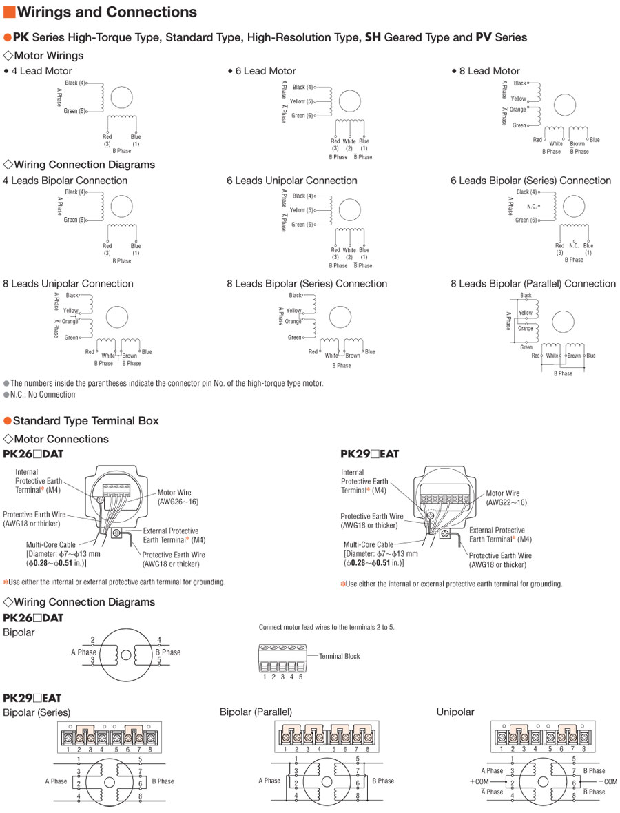
Following is an example of the motor with good data sheet in which motor has connector

Credit: Oriental Motor
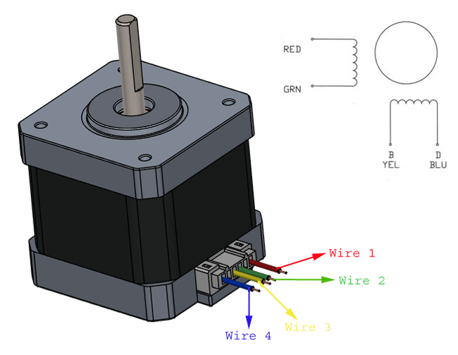
Following is the example of good is which motor has wire coming out of stepper motor.

If you have any of the above diagram for your motor, we are basically done here, just look at these diagrams, look at the datasheet of motor driver and make the connection. Or you can match this with the naming convention diagram and make connection according to that.
If there is no datasheet, you have two option:
- Tryout the connection assuming connection shown in datasheet example or use the images given below
- Use multi-meter to figure out which connection are one coil
Other connection

Credit: components101.com

Credit: components101.com

Credit: components101.com
Using multi-meter to figure out which wire connect to which coil
You should know how many phase (how many coils) a motor has.
Each coil will either have 2 wires or 3 wires
So assuming it's a 2 phase motor, it will have two coil. In this case it will either have 4 wires on 6 wires coming out of the motor

First take a multi-meter and set it on resistance mode
Now you need to check resistance across the pins/wires to check which pins are connected to same coil, following is how they should behave:
- Resistance across 1/2/3 and 4/5/6 will be infinite
- Resistance across 4 and 5 or 5 and 6 will be half of resistance across 4 and 6
- Similar to point 2, pair of 1,2 and 3 will behave
Closing
To sum up, following are the steps:
- Figure out which pair connectors/wires coming out of stepper motor connects to same coil using
- Connection naming from datasheet
- Trying commonly famous connections shown above
- Using a multi-meter
- In motor driver datasheet, find out which pair of pin are pair of H-Bridge
- Make sure to connect one coil to one H-Bridge
If there are questions or feedback please do comment below, it will help be improve the blog as well!
External resource
- Highly recommended video to see how everyday use stepper motor is constructed and works: https://www.youtube.com/watch?v=6jkcoQ92cFk
- Stepper motor working: https://www.haydonkerkpittman.com/learningzone/technicaldocuments/stepper-motor-theory
- H-Bridge working: http://www.modularcircuits.com/blog/articles/h-bridge-secrets/h-bridges-the-basics/
- More on wiring: https://ebldc.com/?p=253
- More on wiring: https://caggius.wordpress.com/stepper-motor-wiring-conventions/
- More on wiring: https://catalog.orientalmotor.com/Asset/con_pk2.jpg
- More on wiring: https://components101.com/sites/default/files/component_pin/NEMA34-Stepper-Motor-Pinout.png
- Motor datasheet: https://www.orientalmotor.com/products/pdfs/2015-2016/A/1.8_PKP_Series-Motor_Gear_Only.pdf
- Motor datasheet: https://www.orientalmotor.com/products/pdfs/opmanuals/HM-7426-3JE.pdf
- Motor datasheet: https://www.omc-stepperonline.com/download/17HS15-1504S-X1.pdf
- Extra details of stepper motor working and comparison of 5 phase and 2 phase: https://www.orientalmotor.com/stepper-motors/technology/2-phase-vs-5-phase-stepper-motors.html
- Image sources: https://components101.com/motors/nema34-stepper-motor
- Image sources: https://in.pinterest.com/pin/317151998745260430/
I always check these types of advisory post and I found your article.230 V Industrial Electric Motors For Sale This is a great source to increase knowledge. Thanks for sharing an article like this.
ReplyDeleteThanks for the kind words!
DeleteGreat post, Thanks for sharing this wonderful blog with us. I love your blog for Custom soft magnetics for sale online in USA .This is very useful and informative post .Keep it up.
ReplyDeleteGenuinely good post about your experience. Your post is interesting to read. I like your writing method, Please share some about Neodymium magnet manufacturer Good luck with next upcoming update.
ReplyDeleteAt Belterra Casino Resort, you’ll discover greater than 900 of essentially the most fun and exciting slot machines, complete with denominations from $0.01 to $100, Video Poker, and two High-Limit slot rooms. We are additionally excited to offer a non-smoking 점보카지노 section for guests wishing to gamble in a smoke-free environment in our Indiana Casino. Be positive to additionally examine again typically to see our featured slots beneath. Many slot machines in a specific on line casino could be linked together to more rapidly grow the progressive jackpot.
ReplyDelete